

Related Concepts
Manufacturing Data
| Material | 18mm raw MDF |
| Tool | 6mm Compression End Mill |
| RPM | 18000 RPM |
| Feed Rate | 4500 mm/min |
| Pass Depth | 18mm one pass |
| Machine Time | ~40 minutes |
| Assembly Time | ~ 15 minutes |
| Machine Type | SMART-MAXSPEED-2137 CNC Router |
| CAM Software | Aspire |
Build Summary
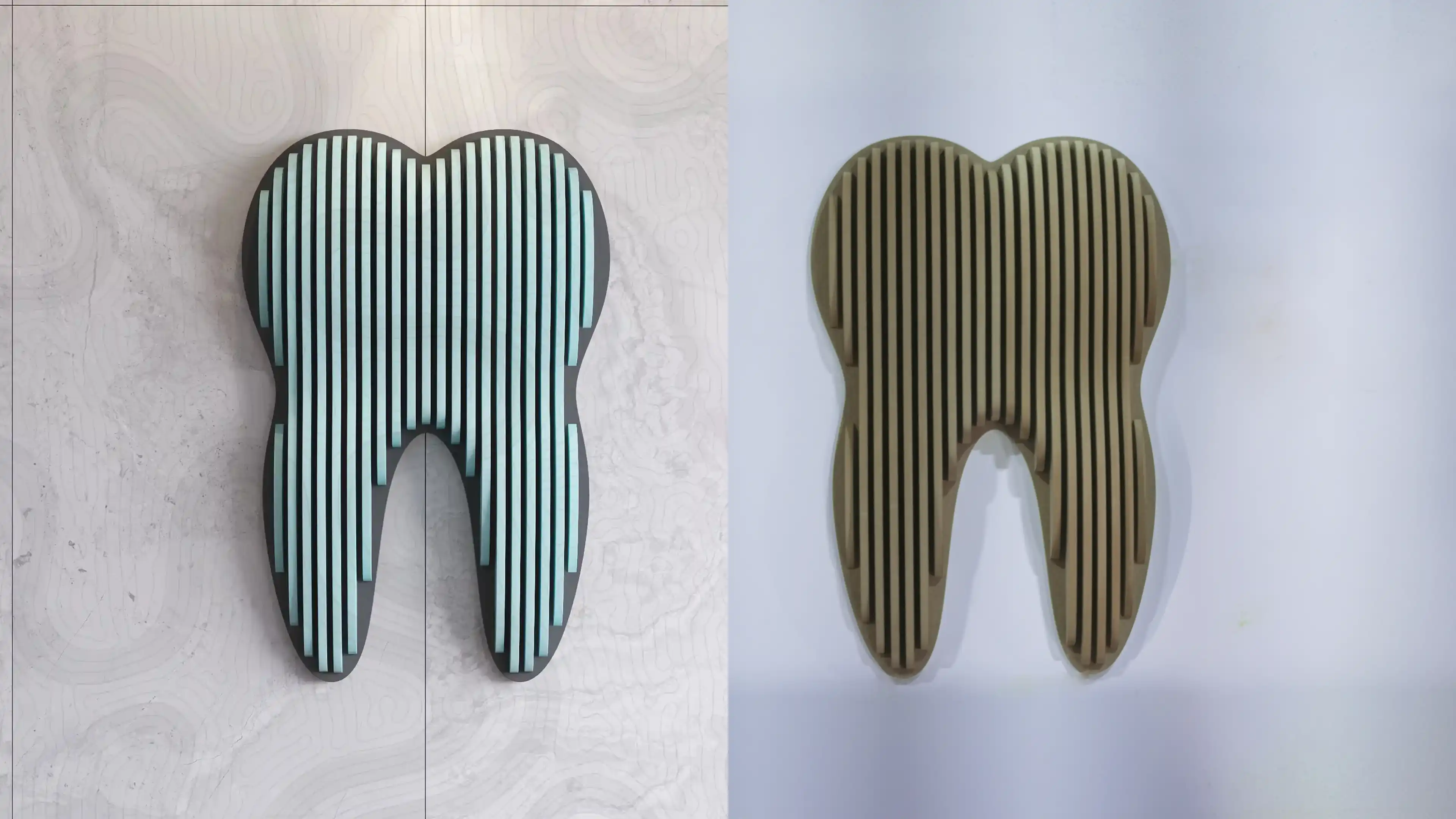
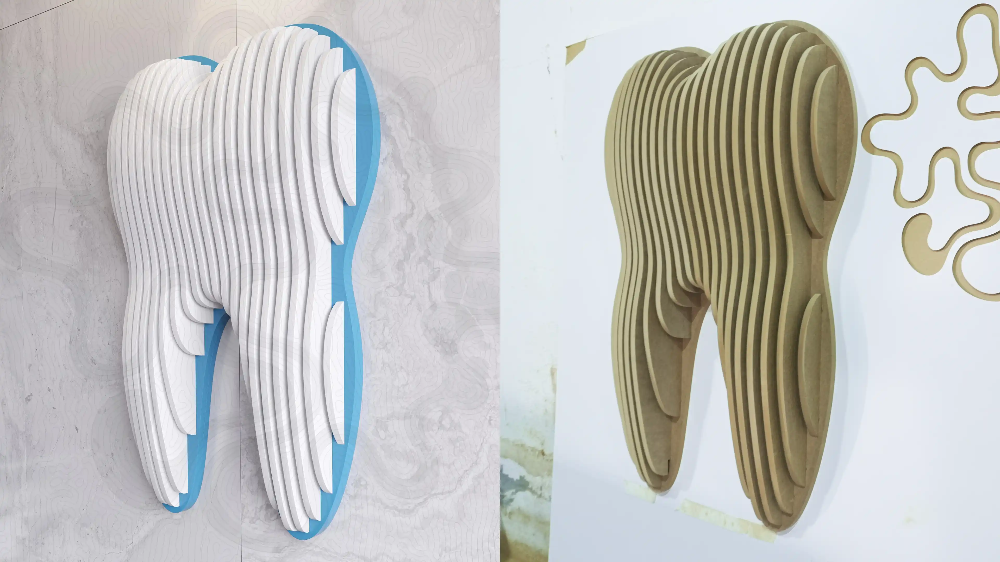
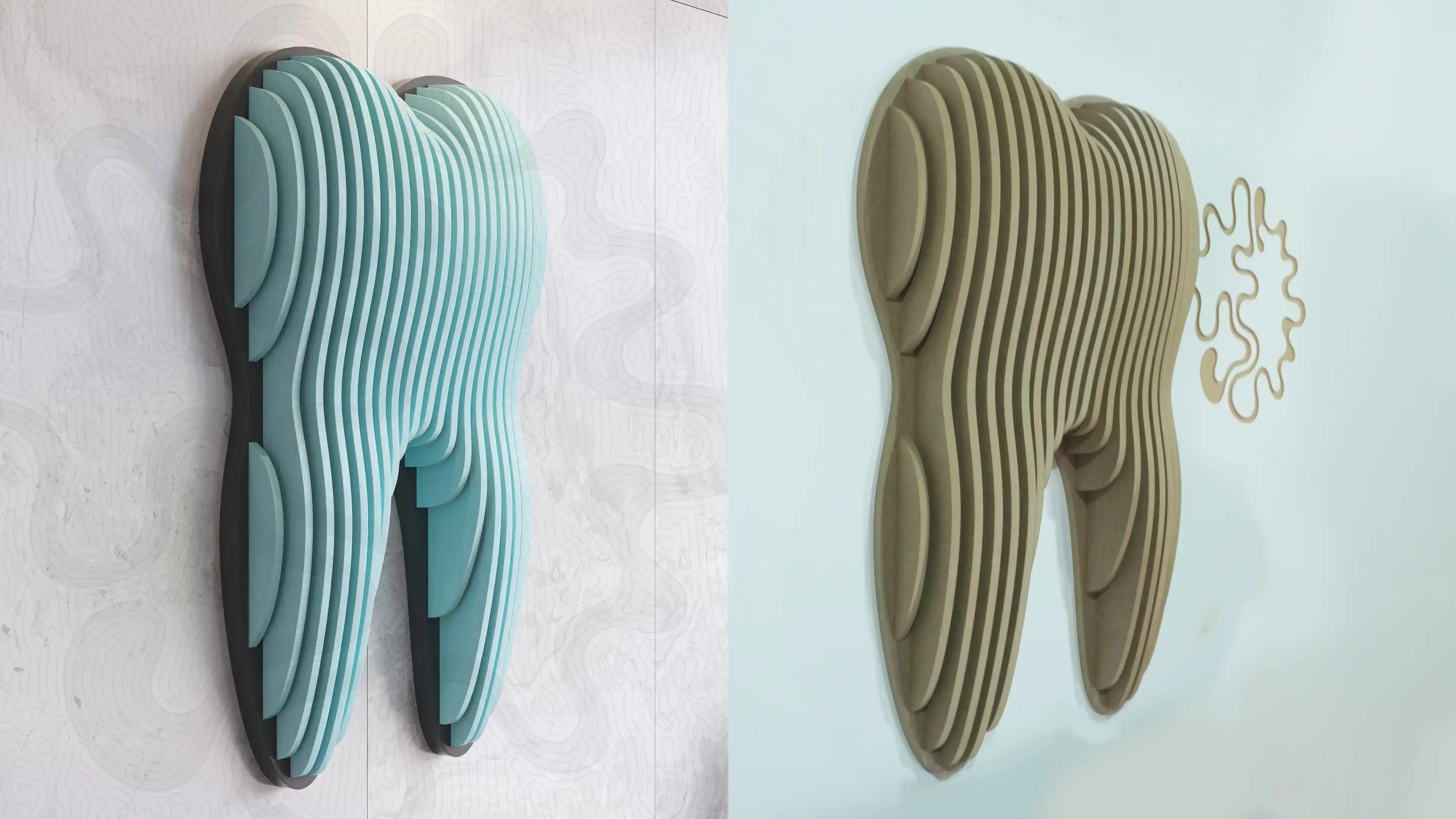
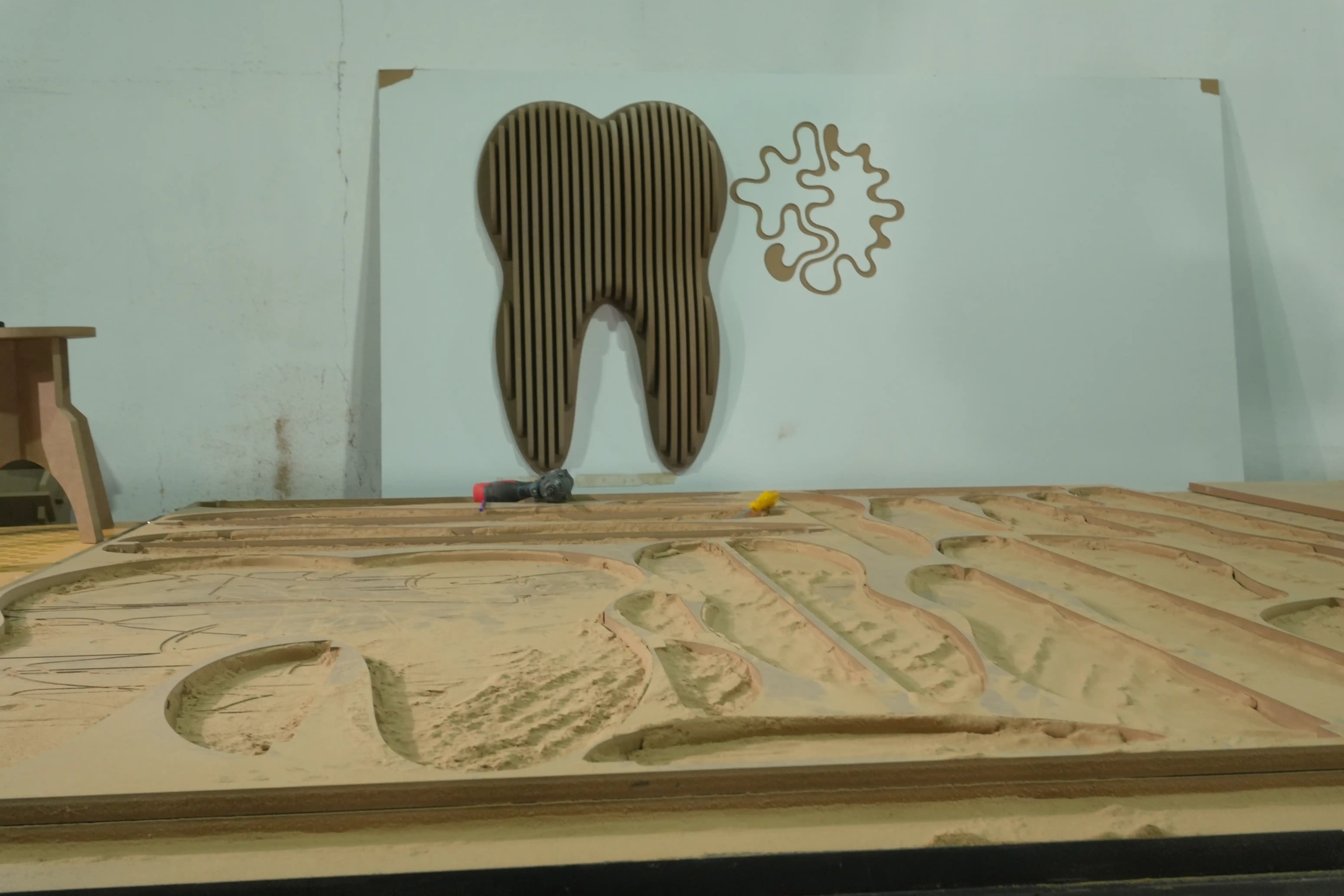
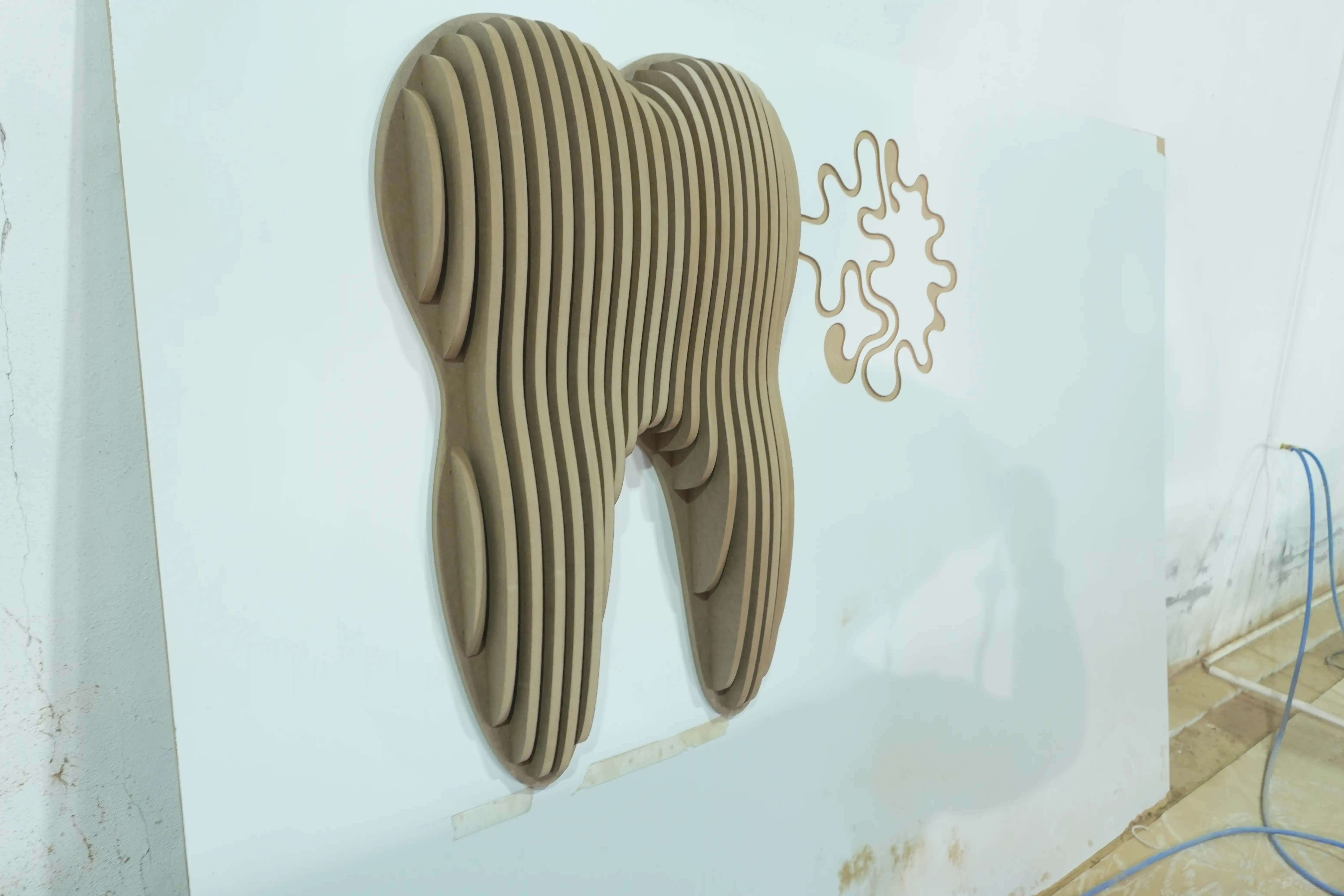
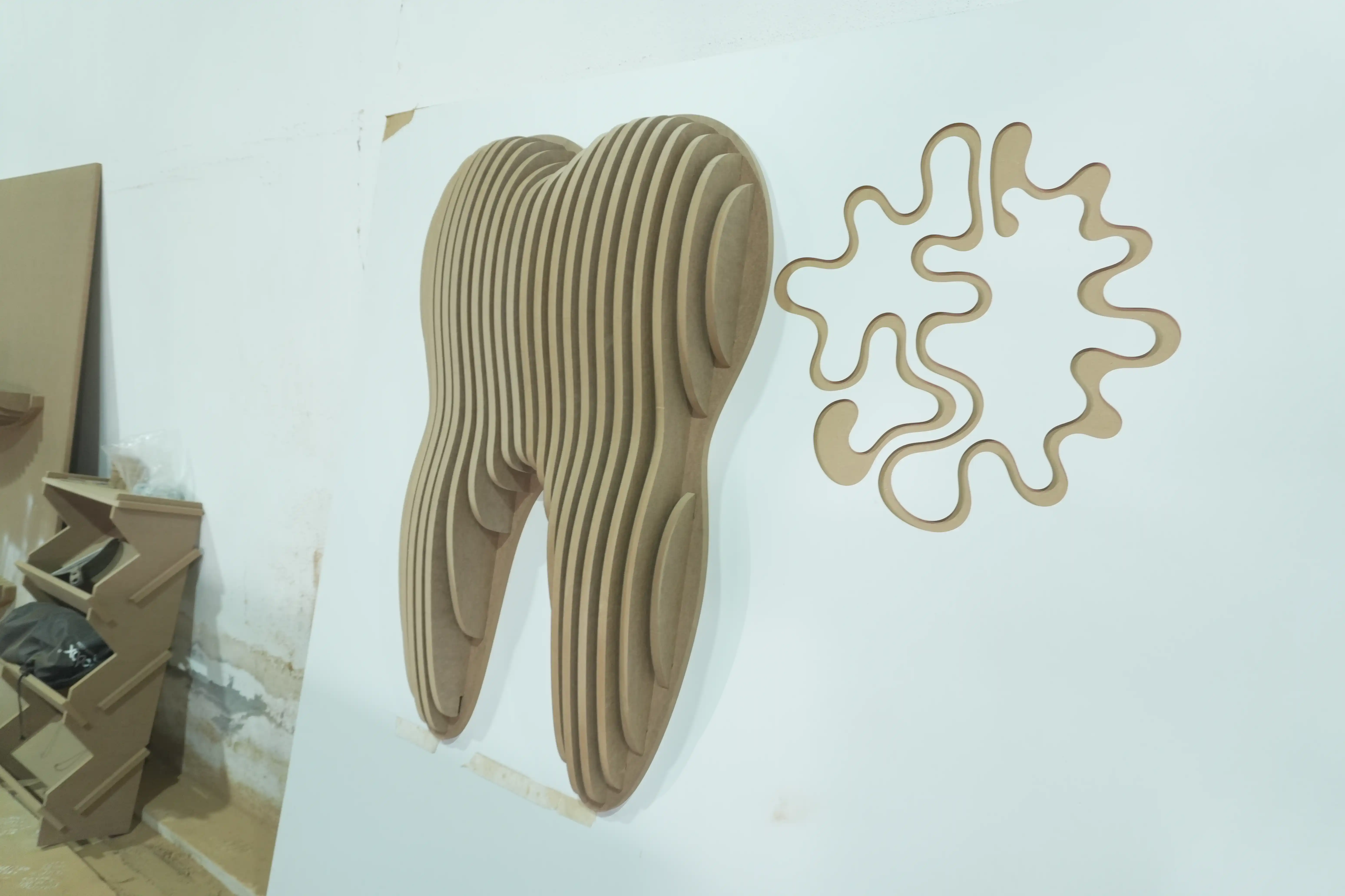
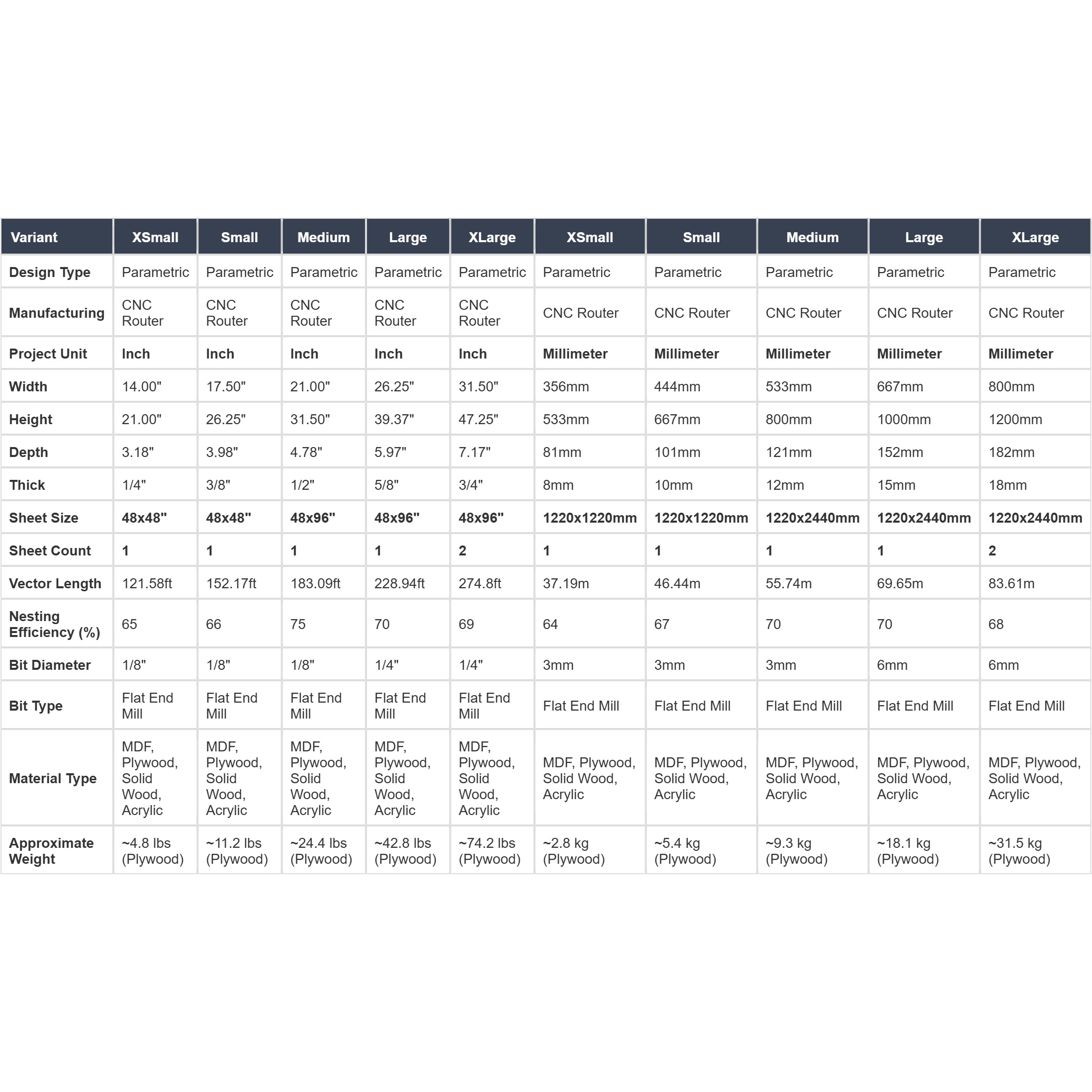
Production build documentation for Parametric Wall Art A-5, a layered CNC wall sculpture designed using contour-based parametric fabrication principles. The project uses stacked vertical profiles to create a dimensional tooth-inspired wall composition optimized for CNC router manufacturing workflows. Its simplified layered geometry allows efficient machining while still producing strong depth, shadow transitions, and sculptural surface effects. The design was prepared as a scalable digital fabrication system with multiple size variants ranging from compact decorative formats to large architectural wall installations. All versions were optimized for sheet-based CNC production using standard 3mm and 6mm tooling workflows and fabrication-ready vector layouts. The project is suitable for MDF, plywood, solid wood, and acrylic manufacturing applications.
Fabrication Notes
Stable vacuum hold-down during machining is recommended due to the large number of thin vertical contour sections used in this project. If vacuum capacity is insufficient, smaller profile sections should remain connected to the sheet material using holding tabs or bridge connections during cutting operations. Internal corner compensation and slot clearances were prepared for 3–6mm flat end mill tooling based on the project specifications. Using tools larger than the recommended diameter for the project size may cause assembly and contour alignment issues in narrow transition areas. The layered structure relies heavily on correct profile sequencing during assembly. Labeling parts immediately after machining is recommended to simplify assembly and reduce alignment mistakes. If raw MDF is used, primer and sealing operations should be applied shortly after machining to reduce moisture absorption and dimensional swelling. Humidity-related expansion may affect layer spacing and assembly fit over time. Interlocking and alignment sections include approximately 0.3mm tolerance compensation clearance on both sides. If paint, primer, veneer, or thick surface coatings will be applied, offset adjustments before machining are recommended to preserve final assembly tolerances. Large-scale versions may require reinforced wall mounting depending on selected material weight and installation surface. For assembly, parts may be fixed to the main back panel using adhesive or screws.